Download document () of 20
Download
You have exceeded the download limit
An automatic transfer switch (ATS) is a self-acting, intelligent power switching device governed by dedicated control logic. The principal purpose of an ATS is to ensure the continuous delivery of electrical power from one of two power sources to a connected load circuit (electrical equipment – lights, motors, computers, etc.).
The control logic or automatic controller is typically microprocessor-based and constantly monitors the electrical parameters (voltage, frequency) of primary and alternate power sources. Upon failure of the connected power source, the ATS will automatically transfer (switch) the load circuit to the other power source (if it is available). As a general rule, most automatic transfer switches seek connection to the primary power source (utility) by default and will only connect to the alternate power source (engine-generator, backup utility) when required (primary source failure) or requested to do so (operator command).
Utility-Generator
The standard transfer switch configuration includes an electric utility service and a generator for normal and emergency power sources. This system arrangement is typically referred to as an emergency standby generator system. The single generator shown may be several engine-generator sets operating in parallel.
Utility-Utility
This use case employs two utility sources that provide redundancy in the distribution system and allows for quick restoration of service to the load if an upstream equipment failure occurs. The two sources can be independent of each other, requiring the public utility company to provide dual electric services, or they can originate from a single electric service that is distributed through redundant paths within the facility.
Generator-Generator
Transfer switches, at times, are applied between two generator sets for prime power use, often at remote installations. In such cases, the generator may be required to provide continuous power 24/7. To equally share run-time, source power is periodically alternated between the generator sets.
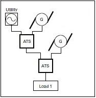
Utility—Generator—Generator
Critical facilities with an emergency standby generator system will often include provisions for a second generator connection to serve as a redundant emergency backup that can be used during periods of inclement weather, or when scheduled maintenance is being performed on the first generator.
As shown, in some cases, the first generator is permanently installed onsite whereas the second generator will be a portable roll-up type that is deployed when needed.
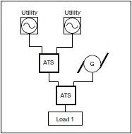
Utility—Utility—Generator
This configuration expands on the redundancy provided by a dual utility arrangement and includes an emergency standby generator source. As shown, the generator can be dedicated for use by a single transfer switch or shared among multiple transfer switches employing a priority control scheme.
Transfer switches transition loads between normal and emergency power sources with open or closed options. The specific functions performed by a given load and the importance of those functions to safety or security play an important role in determining which kind of transition is required.
Open transition
An open transition is a break-before-make transfer. The transfer switch breaks its connection to one power source before making a connection to the other. Open transitions include open-delayed and open in-phase.
Closed transition
A closed transition is a make-before-break transfer. The transfer switch makes a connection to a second power source before breaking its connection with the first power source. As there’s no gap between disconnection and connection, downstream loads receive continuous power throughout the transfer process.
Manual |
Transfer initiation and operation are performed manually, typically by pushing a button or moving a handle; initiation occurs locally |
Non-automatic |
Manually initiate a transfer by pressing a button or rotating a switch to cause an internal electromechanical device to electrically operate the switching mechanism; initiation can occur locally or remotely |
Automatic |
Transfer switch controller is self-acting and completely manages both initiation and operation; initiation is triggered when the automatic controller senses an unavailability or loss of source power followed by operation of the switching mechanism |
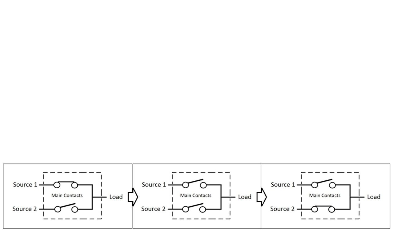
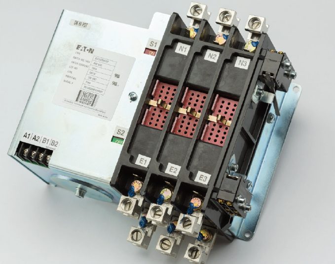
Contactor type
This is the most common and typically most economical switching mechanism type. Contactors are constructed as an electrically-controlled, double-throw switch where a single operator opens one set of power contacts while closing a second set.
Molded case type
Routinely used for closing and interrupting a circuit between separable contacts under both normal and abnormal conditions, molded case switches feature simple designs and are capable of supporting either a mechanically operated, over-center toggle or a motor operator.
Power frame type
Power frame switches are larger, faster and more powerful than molded case switches, and are capable of handling up to 5,000 amps. A two-step stored energy technology is utilized that permits manual and electrical operation under load.
Switched neutral
For three-phase power applications requiring that the neutral conductor be switched, transfer switches can be configured with a fully-rated fourth pole that performs identically to the individual phase (A, B, C) power poles. For single-phase applications, a fully-rated third pole can be configured. A switched neutral is commonly used when the transfer switch is fed by separately derived power sources.
Bypass isolation automatic transfer switches
For simplified maintenance and improved uptime, bypass isolation automatic transfer switches provide dual switching functionality and redundancy for critical applications. The primary ATS handles the day-to-day distribution of electrical power to the load, while the bypass switch serves as a backup or redundant device.
A bypass isolation transfer switch is frequently selected for use in healthcare and other critical applications because it allows the ATS, and in some cases the bypass switch, to be drawn out and isolated from the power source(s) to facilitate regular maintenance, inspection and testing as prescribed by code (NFPA 110).
Service entrance transfer switches
Facilities with a single utility connection and a single emergency power source will often have an ATS located at the service entrance to ensure that critical loads can quickly and safely shift to emergency power if utility power is interrupted. Non-critical loads are often inhibited or shed from connection to the emergency power source to avoid capacity overload.
Ratings
When applying a transfer switch for use in a power distribution system consideration must be given to the withstand closing current rating (WCR) to ensure system integrity and reliability. The UL1008 standard permits transfer switches to be marked with one or more short-circuit and/or short-time WCR’s specific to an overcurrent protection device type. Transfer switches with multiple ratings provide greater application flexibility.
Learn about the Eaton Power Systems Experience Center (PSEC) - a training facility where engineers and electricians can see the latest advances in electrical power quality, energy management and safety, and test products in a safe environment.
Electrical safety requires periodic testing and maintenance for switchgear, breakers, transformers and electrical equipment. Learn about ductor, megger, hi-pot and typical electrical testing methods at Eaton's Experience Center.