Download document () of 20
Download
You have exceeded the download limit

 MyEatonFAQs
Abstract— This paper describes the design and operation of the microgrid installed for the US Department of Defense at Fort Sill, Oklahoma. The microgrid is composed of two natural gas generators, a battery energy storage inverter, renewables, and a static switch. Design considerations for this retrofit application with a high penetration of dynamic loads are given. The integration of the energy storage inverter with a commercial isochronous generator control system is described. A comparison of droop control vs. isochronous control is provided, and the benefits of using an existing isochronous generator control system for microgrid applications are described. System performance is validated by simulation results.
I. INTRODUCTION
The Department of Defense (DoD) is interested in microgrids for improving energy security, reducing fuel cost and resupply convoy casualties, and increasing alternative and renewable energy use. Energy security is of significant concern for the DoD. The DoD needs to be able to continue operating in case of outages caused by a deliberate attack on U.S. power grid, “Katrina-type” natural disasters, or aging grid infrastructure and equipment failure. Microgrids are seen as a coordinated approach to maximize energy security and minimize cost and environmental impact.
Microgrids allow islanded or grid-parallel operation and can include features such as seamless transfer between gridconnected and islanded operation, priority based load shedding, extended islanded operation, and power export.
There has been a great deal of research on microgrids, but there is a shortage of demonstrations of large-scale microgrids for DoD applications. The Fort Sill Microgrid demonstrates a full-scale DoD microgrid with features including seamless transfer between islanded and gridconnected operation, energy storage, renewables integration, load shedding, and power export. The maturity of microgrid technologies for DoD deployment are a concern. This project takes the state-of-the-art microgrid controls as a starting point, specifically CERTS microgrid controls [1, 2], and builds on them to improve the level of maturity and to demonstrate a full-scale DoD microgrid. One significant innovation in this project from the perspective of microgrid maturity is adapting a conventional generator control system for monitoring and control of a microgrid with generators and inverters, as opposed to developing the system-level controls and monitoring software from scratch.
This microgrid is unique from existing microgrid test beds in that all of the loads are dynamic loads with nonlinear or high-inrush characteristics, which are significantly more demanding than the linear loads typically used in test beds. This mix of high-inrush and non-linear loads is representative of what the authors anticipate to be common for practical microgrid installations. The experience gained from this project is useful for outlining challenges and design considerations for future DoD and industrial microgrids. Retrofit applications will typically have added costs, because of limited control over the type of loads present, and potentially limited control over the loads themselves. It is anticipated that almost all DoD microgrid applications will be retrofits. The remainder of this paper is organized as follows: A system description is given in Section II, the microgrid operating modes and design considerations are described in Section III, the integration of the energy storage inverter into the isochronous generator control system is described in Section IV, simulations of starting the large induction motor are shown in Section V, protection is described in Section VI, and conclusions are given in Section VII.
II. SYSTEM DESCRIPTION
The microgrid described in this paper is located on Fort Sill, Oklahoma. It is composed of two 240 kW natural gas generators; a 500 kVA inverter with a 400 kW, 56 kWh lithium ion (Li-ion) battery; a 1200 A, 480 V static switch; 20 kW of PV; a 2.5 kW wind turbine; and local loads. The loads are composed of a 360 hp induction motor (IM) with a wye-delta starter, a 200 hp rectifier-fed variable-frequency drive, and miscellaneous small induction motors and lighting loads. A one-line diagram is shown in Fig. 1.
III. MICROGRID FEATURES AND DESIGN CONSIDERATIONS
A. Operating Modes and Transitions Islanded operation is initiated in two difference ways:
islanded operation can be initiated intentionally, or in response to a grid disturbance. With intentional islanding, the generators are brought online and ramped up to assume the entire microgrid load. When the static switch current is near zero, the static switch is opened and a smooth transition occurs with no voltage or frequency transient. In the case of unintentional islanding, the generators are typically offline, and the load is immediately picked up by the inverter once the static switch opens. When a grid fault or some other type of grid disturbance occurs, the static switch opens suddenly, and the microgrid load must be supported by the inverter. The inverter is always online and ready to pick up the load, assuming sufficient battery state of charge. Once the static switch is opened, the inverter supports the entire load until the generators are started. The generators synchronize to the inverter and ramp up their output power to assume the entire load. If there is sufficient capacity, the inverter can begin charging.
The isochronous control system can allow for various grid-connected operating modes, including peak shaving and power import/export. A “renewables leveling” mode of operation has been proposed in which the energy storage can be used to maintain the combined output of PV + wind + energy storage output at a specified level, subject to battery state of charge constraints. The battery can also be used for peak shaving mode, where the battery is used to maintain the microgrid power import at or below a specified level. Use of the synchronous generators for peak shaving or base loading is possible, but has not been exercised in this project. Due to local emissions constraints, the generators are restricted to operation only when the grid is unavailable.
Power export from the microgrid is a desired feature of this microgrid. In this case, the microgrid owner also owns the local distribution system, and thus will allow power export.
Load shedding is enabled, and is facilitated by changing the % load operation point of the 360 hp induction motor. All of the other loads are considered critical and will only be shed in case of a severe under frequency, in which case all loads would be shed. This is a very interesting point, because shedding of non-critical loads is often touted as an important feature of microgrids for improving reliability. However, in real-world microgrids, there may not be many sheddable loads because customers will consider all of their loads to be critical. Including non-critical loads in the microgrid will increase cost, and hence customers will not want to include non-critical loads inside the microgrid.
B. Design Considerations for Retrofit Applications
Retrofit applications have some unique differences from new installations that may have significant impacts on microgrid design and cost. The main difference is limited control over loads, and limited ability to modify the system. In this application, there is a single IM that represents 70% of the normal operating load, which caused significant concerns about tripping off the sources during IM starting and the islanding transition. It would have been preferable to add a variable frequency drive to the IM to reduce inrush, but that was not an option due to the project being a retrofit. It would also have been preferable to overrate the sources due to the large starting inrush, but cost constraints prohibited this. Instead, generation overhead margin was reduced in favor of cost, necessitating a special procedure for starting the IM. While the total load rating is above the generator capacity, the typical maximum load is slightly below the generator capacity, which allows the use of the selected generator ratings.
Considerations such as high penetration of dynamic loads, limited control over loads, and retrofit applications are likely to increase the required peak ratings of sources, thus increasing the cost of microgrids and impacting their economic viability.
IV. INTEGRATION OF INVERTER INTO ISOCHRONOUS GENERATOR CONTROL SYSTEM
A. Basics of Modern Isochronous Control
Synchronous generators have only two control inputs: governor speed reference, and AVR terminal voltage reference. Isochronous control systems use the speed and voltage bias inputs on the governor and AVR to control the generator. Increasing the speed reference causes the governor to increase the speed by increasing mechanical input power. If connected to a stiff grid, the speed is fixed by the grid and increasing mechanical input power will increase electrical output power. Increasing the voltage reference causes the AVR to increase the terminal voltage by increasing the field excitation. If connected to a stiff grid, the terminal voltage is (mostly) fixed and increasing the
field excitation will increase reactive power output. When in an island with multiple generators, increasing the speed (or voltage) reference of one generator will have the effect of both increasing its real (or reactive) power output (and thus changing the relative load sharing between the generators), and increasing the system speed (or voltage).
With knowledge of the power output, voltage, and frequency of each source (via communication), an isochronous control system can adjust the voltage and frequency bias of each source to simultaneously regulate the dispatch of each source and system voltage and frequency. A basic diagram of an isochronous controller applied to a synchronous generator is shown in Fig. 2. Various control modes and control objectives are possible. In grid connected mode the total grid power import/export can be controlled, and the generators can be used for base load or load following. In islanded mode the generators can share load proportionally, or some used for base load and others for load following.
B. Benefits & Drawbacks of Droop vs. Isochronous Control
Droop control provides stable load sharing without communication. However, communication is required for system wide monitoring, control, & optimization. Without communication, only stable, proportional load sharing is possible. With droop control, the system voltage and frequency may deviate significantly from rated values, potentially causing problems for certain types of loads. Operation at rated voltage and frequency is possible with communication and a system control that adjusts droop parameters to restore voltage and frequency to nominal values.
Isochronous control allows a great deal of flexibility in the control of each source, and allows operation at rated voltage and frequency. Isochronous control systems allow control of the real and reactive power set points of each source, enabling a wide variety of control modes including proportional load sharing, operation of one or more sources in base loading mode, power import/export, and peak shaving. Isochronous control inherently provides continuous supervisory control. Existing isochronous control systems can provide system-wide monitoring, control, optimization, and display. The primary drawback is that communication is required for control.
Droop control allows for stable operation in the event of communication failure. However, isochronous control systems are widely used for critical power systems such as hospitals and data centers, despite relying on communication. The isochronous control product line used for this project utilizes dual-redundant Ethernet networks, and has never experienced a single communication failure (of either of the redundant Ethernet networks, let alone a dual failure) in years of service in numerous applications. Therefore, contrary to the consensus of the microgrid literature, relying on communication for control is not necessarily a problem – it has been done for years with few (or zero) problems. However, isochronous control systems are typically configured such that if a controller does detect a communication failure, then it reverts to droop control.
Using an existing control system minimizes development costs because the existing isochronous control system already has nearly all of the desired monitoring & control functionality. The existing control system also has secure interface options that incorporate information security concerns and allow addition of advanced optimization techniques.
C. Integration of Inverter with Isochronous Control System
The isochronous controller generates real and reactive power references that are implemented by the voltage and frequency bias controllers. When grid connected, or when islanded with synchronous generators online, the inverter can operate in power control mode with the power references given by the isochronous controller. For the islanding transition, the inverter should be able to support the grid immediately after the PCC switch is opened. The inverter must be able to operate in standalone mode if no generators are online. DQ current control is typically used for power control. However, dq current control uses a phase-locked loop (PLL) and requires that another source be present to regulate voltage and frequency [3].
Another way to regulate power is by adjusting the inverter’s phase angle to control real power and adjusting the voltage magnitude to control reactive power. Standalone operation can be achieved by regulating voltage magnitude instead of reactive power and operating at a constant frequency, i.e. keeping the angle constant.
The inverter control used in this work is shown in Fig. 3. When grid-connected, reactive power is regulated by a PI controller, the output of which is the inverter voltage magnitude command. When islanded, the voltage magnitude command is obtained from regulating the output voltage magnitude. In standalone mode, i.e. when islanded and the generators are offline, the inverter angle is held constant.
When grid-connected or when islanded with the generators online the real power is regulated by changing the angle. Note that with the control mode selections in Fig. 3, ‘standalone’ is true (equal to 1) when the inverter operates by itself in islanded operation, and ‘islanded’ is true when the static switch is open. Different sets of PI gains are used for grid-connected and islanded operation.
The integration of this voltage controlled inverter with the isochronous control system allows various methods of dispatching the inverter and generators, as well as seamless transitions between grid-connected and islanded operation.
D. Simulation Results
Simulations have been performed to demonstrate the basic functionality of the proposed inverter control method and its integration with the isochronous control system. The mode transitions from grid-connected to islanded (standalone), and islanded to parallel with generators are also demonstrated. Simulation models of the generators were based on a proprietary model of a large, turbocharged diesel generator, and the inverter model is based on the inverter used in the project with the control shown in Fig. 3. The simulations were performed in PSCAD and included a detailed model of the isochronous control system.
The first simulation demonstrates the effectiveness of the real power control by adjusting the angle, and reactive power control by adjusting the voltage command. A simulation of real and reactive power reference steps when grid-connected is shown in Fig. 4. The real and reactive power controllers track the references with minimal overshoot.
During normal operation, the inverter is grid connected and is ready to support the microgrid in case of a grid outage or disturbance. In the simulation in Fig. 5, the inverter is initially grid connected and is trickle charging the battery, i.e. the angle controller is regulating power and the Vmag controller is regulating reactive power. The VFD load and small IM loads are online, but the 360 hp IM is offline. At 4 seconds, islanding is initiated suddenly by opening the static switch, and the inverter transitions to standalone mode 10 ms later, triggered by status information about the static switch sent via the isochronous control system. In islanded mode the angle is held constant and the Vmag controller
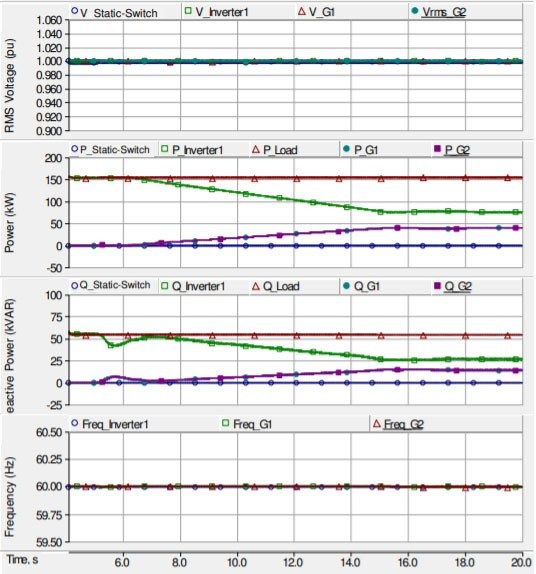
regulates voltage magnitude. Once the inverter is islanded and is in standalone mode, the generators start up and synchronize to the microgrid. A simulation of this procedure is shown in Fig. 6. The isochronous controller slowly ramps up the generators until they have assumed the entire load. The capability to slowly ramp the generators is a convenient feature of isochronous control. After the generators have synchronized and assumed the load, the inverter transitions
out of standalone mode. The behavior of the inverter in power control mode while islanded with the generators online will be explored in the next section.
The isochronous control system provides a completely seamless transition from islanded to grid-connected mode. The isochronous controller connected to the static switch monitors the microgrid and grid voltages and adjusts the references for the inverter and generators to synchronize the microgrid voltage, frequency, and phase to the grid prior to closing the static switch. After the static switch closes, the output power of each source does not change, and the static switch current is nearly zero because the microgrid voltage, frequency, and phase were matched to the grid prior to closing the static switch.
Isochronous control provides a completely seamless transition from grid-connected to islanded mode, whereas simple droop control does not. With simple droop control, synchronization is achieved by operating the microgrid at a different frequency from the grid, and waiting until the voltage across the breaker passes through zero [4]. After the breaker closes, the frequency, and thus the power output of each source, changes. Under ideal conditions this transient may be small, but isochronous control can provide a completely seamless transition.
V. HIGH PENETRATION OF DYNAMIC LOADS
Real-world microgrids will typically have dynamic loads such as high inrush motors and non-linear rectifier loads, with different requirements than the linear loads normally used in microgrid test beds. The loads in the microgrid described in this paper consist of induction motors (IMs) and a large variable frequency drive fed by a diode rectifier. The 360 hp IM represents a large percentage of the total load, and the inrush characteristics are very important to ensure that the microgrid is capable of starting it during islanded operation.
A. Inrush Characteristics of the 360 hp IM
The 360 hp IM has a wye-delta reduced voltage starter [5], which configures the stator windings in wye during startup, and transitions to delta once the machine reaches near rated speed. The wye-delta starter results in starting current and torque of 1/3 that of starting across-the-line in delta. When the stator windings are transitioned from wye to delta, a large inrush occurs that can have a peak current nearly as high as the delta locked rotor current. The PSCAD model of the 360 hp IM is shown in Fig. 7, and utilizes a 6- terminal IM model and contactors and transition resistors to transition between wye and delta connection. Contactors M1, M2, S1, and S2 are sequenced as in [5] to transition the connection from wye to delta. The input ‘StoT’ is used for initialization to transition from user specified (fixed) speed ‘W0’ to user specified (calculated) load torque ‘T_shaft’.
The inrush characteristics of the 360 hp IM were measured prior to the installation of the microgrid, and were used to validate the simulation model. A comparison of simulation and measurement results is shown in Fig. 8. Fig. 8(a) shows the RMS inrush current, which starts at 750 ARMS,. Fig. 8(b) shows a close-up of the wye-delta transition, where the peak current exceeds 2,700 Apeak, or 220% of the combined rated currents of the generators and inverter.
The inrush measurements were used to validate a simulation model, and simulations were performed to ensure that the inverter and generators would be able to start the IM without suffering from an overcurrent trip.
B. Simulation of IM Starting
Due to the large inrush of the 360 hp IM, a special procedure is required for starting the motor. Both generators and the inverter must be online, because neither the generators nor the inverter are capable of starting the motor by themselves. The other microgrid loads, specifically the 200 hp VFD, must be throttled back using the building management system. The building management system makes it possible to inhibit starting of the large IM if the conditions are not suitable.
In this simulation, the inverter and generators are controlled to share real and reactive power in proportion to their ratings. The inverter adjusts its angle to control its real power to share load with the generators, and regulates the voltage to rated value. The IM starting simulation is shown in Fig. 9 and Fig. 10. Initially, the smaller IM loads are online, and the VFD is set to a reduced load level. The 360 hp IM starts at 5.0 seconds, and the inverter initially supplies most of the reactive power, until the generators increase their reactive power output. At 10.27 seconds the IM transitions from wye to delta, and draws a large current surge. The inverter and generator currents are shown in Fig. 10, and it can be seen that the inverter current reaches nearly 1.8 per-unit. This simulation has shown that the microgrid is able to handle the large, high-inrush motor load.
VI. PROTECTION
Protection is a significant concern in microgrids due to the unique challenges encountered in microgrid environments [6-9]. The protection scheme employed in the
Ft. Sill Microgrid is described here to provide a record for microgrid designers of protection systems employed in pilot microgrids. The microgrid uses a static switch as the main protective device, with backup trip function provided by two utility-grade relays, one of which becomes the primary protection when the static switch is bypassed. Overcurrent protection is provided by each source’s breaker (G1, G2, INV, Wind, PV), as well as the inverse time overcurrent protection in the load breakers. Each breaker has inverse time and instantaneous overcurrent protection. The static switch also has over/under voltage and over/under frequency relay to meet IEEE 1547 requirements, as well as a more sensitive over/under voltage settings to provide rapid islanding in case of a utility disturbance.
A protection coordination study was performed to choose the overcurrent relay settings for each of the breakers to provide coordination during faults between upstream and downstream devices. The coordination study considered faults in grid-connected and islanded modes and with different combinations of sources online to consider maximum and minimum fault currents. The same settings for overcurrent protection are used for all operating modes.
The coordination study identified that due to limited fault current capability of the inverter, the downstream breakers may not trip in islanded mode when only the inverter is present. The inverter only operates by itself in islanded mode for a short period, since the generators normally run during islanded operation. The generators are able to provide sufficient fault current to trip downstream breakers. Another concern is that the calculated worst case fault current is very close to the short circuit rating of the static switch.
VII. CONCLUSION
The Fort Sill microgrid provides valuable experience in microgrids designed for seamless transitions between gridconnected and islanded operation, and experience with a high concentration of dynamic and nonlinear loads. It is anticipated that many real-world microgrid installations will be retrofit applications with a high penetration of dynamic loads. This is particularly the case in DOD installations, which will almost all be retrofit. This microgrid improves energy security for the DoD by providing operation during grid outages, seamless transition between grid-connected and islanded operation, and integration of renewables. The integration of a battery energy storage inverter into a commercial isochronous control system has been described. This isochronous control system provides all of the desired microgrid operation, control and monitoring features, with minimal new software development, and includes the ability for integration of advanced optimization methods.